
Micropillar Array
This figure shows a process flow to fabricate molds of micropillars with two different heights.
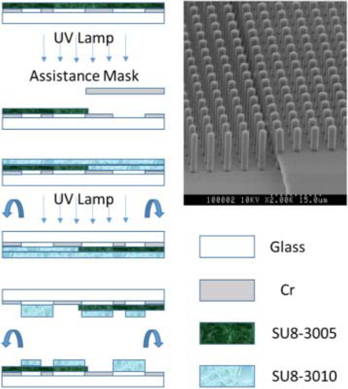
(1) Firstly, periodic holes were patterned on the blank chrome (Cr) mask pre-coated with a photoresist layer (AZ1518) by using a micro-pattern generator (μPG101).
(2) After Cr etching and the resist removal, the Cr mask was spin-coated with a 4-μm thick negative resist layer (SU8-3005). This resist layer was then UV exposed from the front side with another mask, resulting in a Cr mask partially covered by the SU8 resist (exposed).
(3) After development, a 9-μm thick negative resist layer (SU8-3010) was spin-coated on, following by the back-side UV exposure.
(4) As results, two adjacent pillar arrays of 4-μm and 9-μm heights were obtained, as shown by the scanning electron microscopic picture in the figure.
Please refer to the link below for the original article:
http://www.sciencedirect.com/science/article/pii/S0167931716301204

