目录

  • 1 Automotive Basics
    • 1.1 课程介绍及学生自我介绍
    • 1.2 课堂测试
      • 1.2.1 课堂测试:阅读理解
      • 1.2.2 课堂测试——听录音,补全段落
    • 1.3 汽车的总体构造
      • 1.3.1 Brief Introduction to Automobile
      • 1.3.2 Body
      • 1.3.3 engine
      • 1.3.4 chassis
      • 1.3.5 electrics and electronics
      • 1.3.6 课堂测试1
  • 2 internal combustion engine
    • 2.1 principle of operation
      • 2.1.1 发动机工作原理
      • 2.1.2 课堂测试——听录音,补全段落
      • 2.1.3 课堂测试1
    • 2.2 engine block and cylinder head
    • 2.3 pison connecting rod and crankshaft
    • 2.4 valve system
    • 2.5 发动机构造课堂测试
      • 2.5.1 课堂测试——听录音补全段落
      • 2.5.2 课堂测试1
    • 2.6 gasoline fuel system
      • 2.6.1 课堂测试2
    • 2.7 diesel engine(学生翻译篇)
    • 2.8 engine cooling
      • 2.8.1 课堂测试1
      • 2.8.2 发动机冷却系统
    • 2.9 engine lubrication
      • 2.9.1 课堂测试
      • 2.9.2 发动机润滑系统
    • 2.10 emission control
  • 3 power train
    • 3.1 overview of power train
      • 3.1.1 Useful Words
    • 3.2 clutches
    • 3.3 transmission
      • 3.3.1 MT
      • 3.3.2 AMT
      • 3.3.3 CVT
    • 3.4 propeller shaft and universal joints
    • 3.5 final drive
    • 3.6 differential and axle shaft
    • 3.7 传动系(1)
    • 3.8 传动系(2)
    • 3.9 传动系(3)
    • 3.10 课堂测试1
    • 3.11 课堂测试
  • 4 braking system
    • 4.1 basic features of Braking system
    • 4.2 Types of Brakes
    • 4.3 翻译作业
    • 4.4 Anti-lock Braking system for passenger car
    • 4.5 Electrohydraulic braking
    • 4.6 制动系
    • 4.7 课堂测试
  • 5 steering and suspension system
    • 5.1 steering system
      • 5.1.1 Steering Geometry and Handling Characteristics
      • 5.1.2 ​Types of Steering System
      • 5.1.3 Hyaraulic Power Steering
      • 5.1.4 翻译作业
    • 5.2 Suspension
      • 5.2.1 Spring and Shock Absorber
      • 5.2.2 Wheels and Tires
  • 6 electrical system and  new energy vehicle
    • 6.1 ELECTRICAL  AND ELECTRONIC SYSTEM
    • 6.2 (小组翻译)new energy vehicle AND architectuer for autonomous driveing
  • 7 customer reception and customer development
    • 7.1 customer reception
    • 7.2 customer development
  • 8 Information Collection and Automobile Intoduction
    • 8.1 Information Collection
    • 8.2 Automobile Intoduction
  • 9 Price Discussion and Bargain Striking
    • 9.1 Price Discussion
    • 9.2 Bargain Striking
  • 10 Terms of Payment and Settling Complaints
    • 10.1 Terms of Payment
    • 10.2 Settling Complaints
  • 11 Customer Feedback and Maintenance Reception
    • 11.1 Customer Feedback
    • 11.2 Maintenance Reception
  • 12 Vehicle Maintenance and Motor Insurance
    • 12.1 Vehicle Maintenance
    • 12.2 Motor Insurance
Anti-lock Braking system for passenger car

Anti-lock Braking system for passenger car


Anti-lock braking systems (ABS ) are control devices within   braking  systems  prevent the wheels from locking up during  braking.

On initial brake, the brake pressure is raised:  the brake slip  λ increases  and, at the maximum point on the adhesion/slip  urve, it reaches the limit between the stable and unstable ranges . From this pointon, any further  increase in brake pressure or brake torque does not cause any further  increase in the brake  force  . In the stable range, the brake  slip is  largely deformation slip, it becoming  increasingly skidding slip  in the  unstable range.

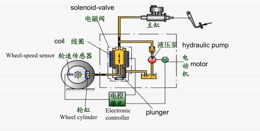
The wheel-speed sensor monitors the motion of the wheel. If one wheel shows signs of locking, there is a sharp rise in peripheral wheel deceleration and in wheel slip. If these exceed defined critical values, the controller sends commands to the solenoid-valve unit to stop or reduce the buildup of wheel-brake pressure until the danger of lock-up has passed. The brake pressure must then be built up again in order to ensure that the wheel is not under-braked. During automatic brake control, it is constantly necessary for the  stability or instability of the wheel motion to be detected, and the wheel must be kept in the slip range with maximum  brake force by a succession of pressure-buildup, pressure-reduction and pressure-holding phases.

A wheel-speed sensor consists of a toothed pulse ring and an inductive wheel-speed pickup. The pulse ring is mounted on the hub and , as the rotates, produces in the wheel- speed pickup an A.C. voltage, the frequency of which is proportional to the wheel speed.

From the signals from the wheel-speed pickups, these microcomputers calculate the wheel speeds as well as the wheel decelerations and accelerations. A vehicle reference speed is formed from the wheel speeds of two diagonally opposite wheels. With this reference speed and the individual wheel speeds it is possible to calculate the brake slip for each wheel. If a wheel has a tendency to lock, this is determined from the wheel-acceleration and slip signals.