clutches

1 dry friction clutch
A dry clutch performs two tasks:
1) it disengages the engine from the transmission to allow for gear changing ,
2) it is a means for gradually engaging the engine to the driving wheels .
When a vehicle is to be moved from rest the clutch must engage a stationary transmission shaft with the engine ; this must be rotating at a high speed to provide sufficient power or else the load will be too great and the engine will stall (come to rest) .
To start the engine , the drive must depress the clutch pedal . This disengages the transmission from engine . To move the car, the driver must reengage the transmission to the engine. However, the engagement of the parts must be gradual. An engine at idle develops litte power . If the two parts were connected too quickly, the engine would stall. The load must be applied gradully to operate the car smoothly .
A driver depresses the clutch pedal to shift the gears inside the transmission.After the driver releases the clutch pedal , the clutch must act solid coupling device . It must transmit all engine power to the transmission , without slipping .
The dry clutch mechanism includes three basic: driving member, driven member and operating member .
1) The Driving Member
The driving member consists of two parts : the flywheel and the pressure plate . The flywheel is bolted directly to the engine crankshaft and rotates when the crankshaft turns. The pressure plate is bolted to the flywheel . The result is that both flywheel and pressure plate rotate together .
2) The Driven Member
The driven member , or clutch disc , is located between the flywheel and pressure plate. The disc has a splined hub that locks to the splined input shaft on the transmisson .Any rotation of the clutch disc turns the input shaft . Likewise , any motion of the input shaft moves the clutch disc . The splines allow the clutch disc to move forward and backward on the shaft as it engages and disengages .
The inner part of the clutch disc , called the hub flange , has a number of small coil springs . These springs are called torsional springs . They let the middle part of the clutch disc turn slightly on the hub . Thus , the springs absorb the torsional vibrations of the crankshaft . When the springs have compressed completely , the clutch moves back until the springs relax . In other words , the clutch absorb these engine vibrations , preventing the vibrations from going through the power train .
3) Operating Members
These are the parts that release pressure from the clutch disc . The operating members consist of the clutch pedal , clutch return spring , clutch linkage , clutch fork and throwout bearing . The clutch linkage includes the clutch pedal and mechanical or hydraulic system to move the other operating member .
When the clutch pedal is depressed , the clutch linkage operates the clutch fork. The clutch fork , or release fork , moves the throwout bearing against the pressure plate release levers . These levers then compress springs that normally hold the clutch disc tightly against the flywheel .
At this point , the torque of the engine cannot turn the transmission input shaft . The gears in the transmission may be shifted or the vehicle can be brought to a full stop .
When the clutch pedal is released , the pressure plate forces the clutch disc against the flywheel . The clutch return spring helps raise the pedal .
2 The hydrodynamic coupling
Most automatic transmissions use a hydrodynamic coupling to join the engine crankshaft to the transmission input shaft. Hydrodynamic couplings and hydrodynamic torque converters transfer the torque through fluid-flow forces . They provide advantages when driving away thanks to infinitely variable conversion of speed and torque, with the maximum torque being available at the drive-away point ( engine turning, vehicle stationary )
The mechanical energy is converted in the pump into the flow energy of a liquid medium ( usually oil ) and is then re-converted in a turbine into mechanical energy by the oil flow being diverted in the vane channel.
The advantages of hydrodynamic couplings include infinite variability , vibration damping ,reduction of torque peaks and virtually wear-free power transfer . Hydrodynamic couplings and converters can be used economically only in conjunction with mechanical multi-step transmissions , because , out of consideration for efficiency , the drive range must be kept within tight speed limits . To prevent excessive slip and thus to improve the efficiency , hydrodynamic power transfer is bypassed by a lockup clutch .
3 The hydrodynamic converter:
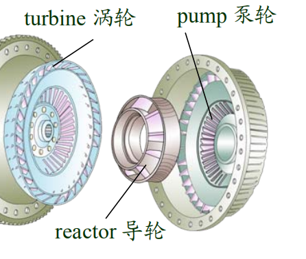
The hydrodynamic converter , also known as the Trilok or Fottinger converter , is capable of operating in two phases: with torque increase in the first phase , and as a hydrodynamic coupling in the second phase. The usual design has three impellers :
1) The pump , which is connected to the engine , acts like a centrifugal pump to produce the flow energy of a fluid .
2) The turbine , which is connected to the transmission input , converts the flow energy back into mechanical energy .
3) The reactor between turbine and pump diverts the flow of the fluid .