Propeller Shaft and Universal Joints
1 Propeller Shaft or Drive shaft
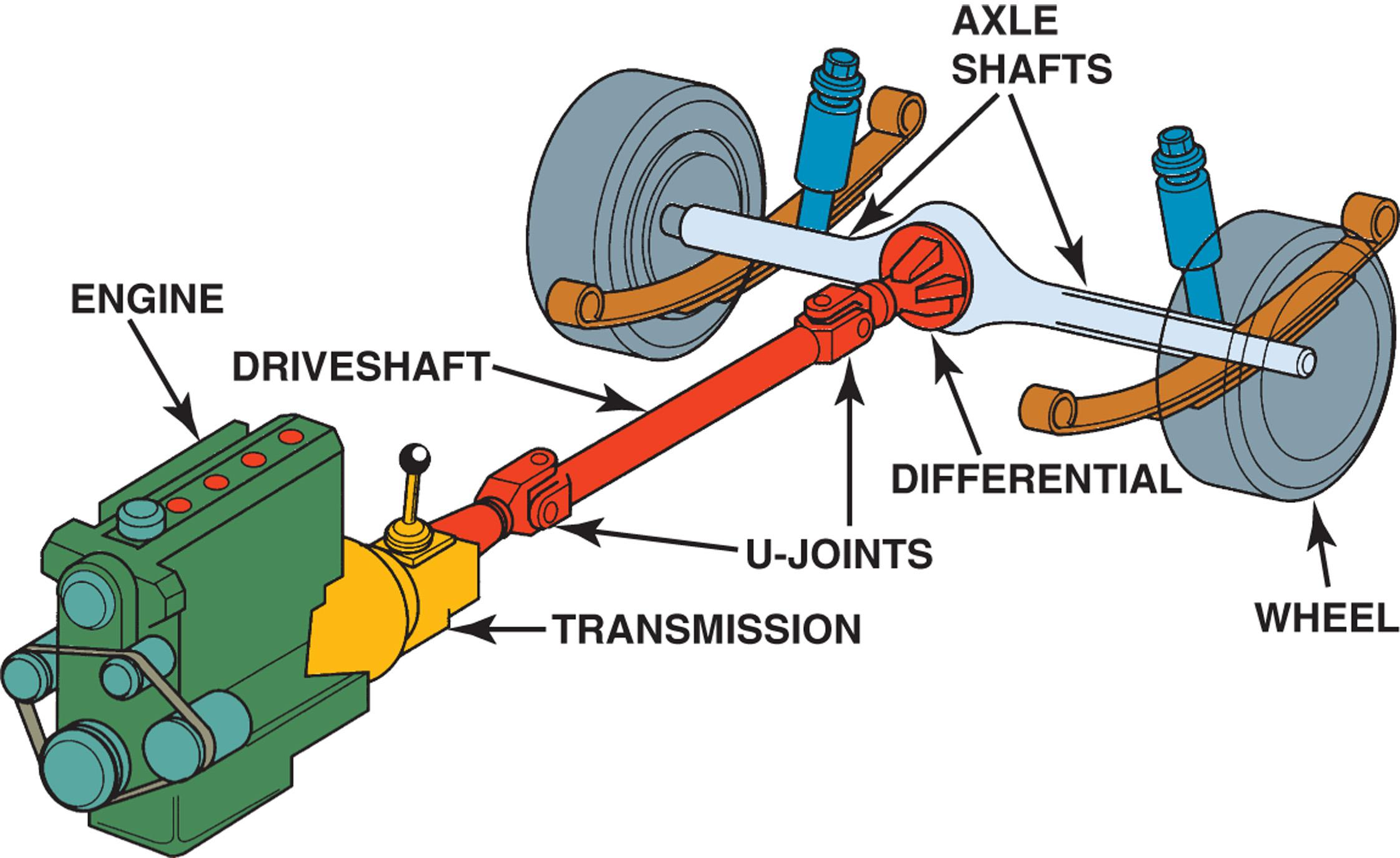
The propeller shaft transmits the the transmission mainshaft to the final drive pinion The shaft is long so it is made of tubular section and balanced to reduce vibration
The drive shaft is not solidly bolted to the transmission and dhe final drive. There must be some allowarice for motion between the final drive and the transmission.
2 Universal Joints
The transmission and engine mount firmly to the car. However, the final drive mounts on springs as part of the rear suspension system. The suspension provides a flexible coupling between the wheels and the car body.
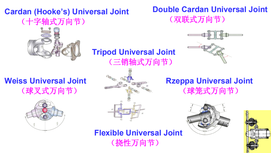
This flexible coupling insulates the car body from the jolts of the road surface. In most automobiles. the rear wheels mount firmly to the axle shafts. The suspension connects the final drive assembly to the car body. The final drive moves up and down in relation to the engine and the transmission. A coupling is needed that permits movement between the final drive and the transmission. The universal joints provide this coupling. There are two types of universal joints——cross type joint and constant-velocity universal joint.
1)cross type joint
Universal joints connect two parts so that either part can move to allow for differences in motion. Fig. shows a simple U-joint. Here two U-shaped pieces are placed perpendicular to one another and joined with a simple . The U-shaped pieces are called yokes. The cross that hects them is called a spider. The arms that extend from the spider are called trunnions
Most vehicles have two U-joints, one at each end of propeller shaft. The reason for is that the simple U-joint is not a constant-velocity joint. This means that its presence between two shafts ,running with angular misalignment , causes a non-uniform rotational speed to be imparted from the driving to the driven shafts.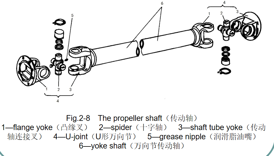
A simple explanation for this peculiarity of operation may be found by observing closely the universal joint during hand rotation of the shafts. It will then be noticed that the cross-piece or spider Hods twice towards the angled driven shaft for each complete rotation. This nodding motion of the spider arises from the fact that although the arms of both and driven yokes rotate m a cirele the projected path of the driven yoke arms describes an owing to the of the dnven shaft( Fig. 321a) . These differing paths of effective movement of the connecting yokes account for there being two positions in which the driven shaft has advanced in rotation relative to the driving shaft and two intermediate positions in which the driven shaft has lagged behind it( Fig. 321b) Each shaft of course, make the same total number of revolutions in a given time despite the in angular velocity.
Retuming now to the vehicle propeller shaft, the effect of this non-uniform rotational speed can be to create an objectiomal vibratign in the drive line, which leads to a general roughness being felt in the car. Fortunately, this peculianity in operation of the U-joint can to all and purposes be countered by the two such joints in series, as is found in the conventional one-piece propeller shaft. With this arrangement, the fluctuations in angular velocity of the swinging propeller shaft are still present but they are canceled the second universal joint before reaching the rear axle final drive shaft.
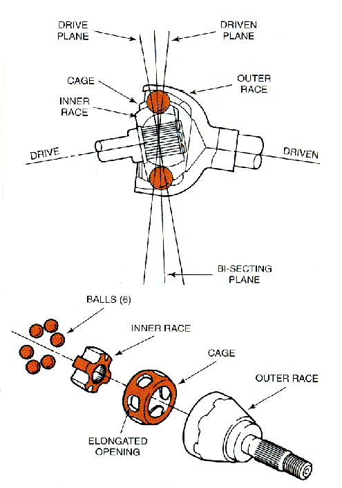
2) Constant Universal Joint
Used at the road wheel end of the the drive shaft of a front-wheel drive vehicle, a constant-velocity joint is capable of giving a smooth drive through large drive angle.
In basie constraction CV joint comprises a ball-and-socket joint with both parts grooved to embrace six rolling steel balls, which are held in a common plane by controlling ball cage. The latter assembly thus constitutes the intermediate member of the joint and must be steered so that the balls always lie in a plane which bisects the angle between the shafts, this being an essential condition for a constant-velocity drive.