
Gasoline fuel system
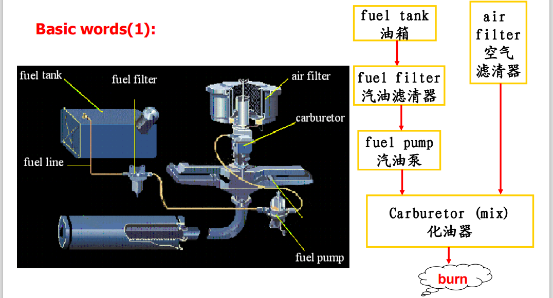

1 Gasoline
Gasoline must vaporize easily. This characteristic, called volatility, is important. However, it must not vaporize too easily, or it will turn to vapor inside the fuel tank or fuel lines. Inside the fuel line, fuel vapor may block the flow of liquid gasoline. This is called vapor lock. Vapor lock is common in fuel lines where the inlet side of the pump is exposed to high temperatures.
Increasing the pressure of the fuel mixture in the combustion chamber before ignition helps to increase the power of an engine. This is done by compressing the fuel mixture to a smaller volume. Higher compression ratios not only boost power but also give more efficient power. But as the compression ratio goes up, knocking tendency increases.
Two primary standard reference fuels, normal heptane and iso-octane arbitrarily assigned 0 and 100 octane number, respectively,are then blended to produce the same knock intensity as the testsample. The percentage of isooctane in blend is considered the octane number of the test sample. Thus, if the matching reference blend is made up of 15% n-heptane and 85% isooctane, the test sample is rated 85 motor or research octane number, according to the test method used.
2 excess-air factor
Petrol will not burn unless it is mixed with air: under ideal conditions the proportion of air to petrol required to burn the fuel completely is 14.7 parts of air to 1 part petrol (by mass). This means that 1 kg of petrol is mixed with 14.7kg of air. The air/fuel ratio needed by a fuel to burn it completely is called the chemically correct mixture. The ratio 14.7:1 applies to petrol; other fuels have different ratios.
To indicate how far the actual,air-fuel mixture supplied to the engine cylinder deviates from the air-fuel ratio(14.7:1) theoretically required for complete combustion,the excess-air factor λ has been chosen:
λ= air mass supplied / theoretical requirement
λ=1 The air mass supplied corresponds to the amount necessary in theory.
λ<1 Lack of air or rich mixture.Increased power output results in the range λ=0.85~0.95.
λ>1 Excess air or lean mixture in the range λ=1.05~1.3. With this excess-air factor, reduced fuel consumption reduced power output occur.
Good transitions occur 15%~25% air deficiency. Transition is defined as the change from a given load range another(e.g. from idle to part or full load). Good transition is usually synonymous with good acceleration. characteristic curves Fig.2-18 and Fig.2-19 show the dependence of power,specific fuel consumption pollutant emission on the excess-air factor λ.as can be seen,there is no single λ at which all the factors are ideal. λ=09~1.1,In practice,excess-air factors of λ=09~1.1 have proven most practical.
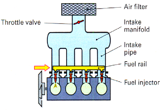
3 multi-point fuel injection
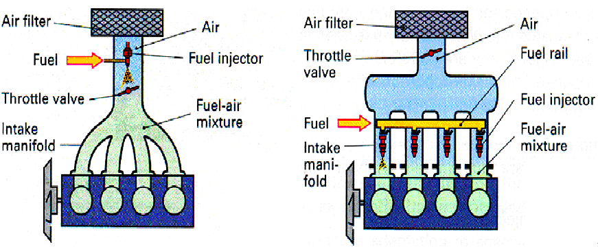
The advantages usually associated with a multi - point fuel injection ( MPI )system , where the fuel is sprayed into the inlet port for each cylinder , are a more uniform distribution of mixture to the engine cylinders, an absence of fuel wetting on the walls of the intake manifold particularly when cold, and the need to design the manifold only for the most efficient of air rather than air and fuel. Another potential advantage is that port injectors can be used with intake manifolds where the separate branches have been tuned in length, so as to exploit inertia ram charging eflects for maximum power.
1) Fuel Flow System
Fuel is drawn from the fuel tank into a roller vane pump driven by an electrical motor of the wet type which means that the motor runs filled with fuel for greater safety in case of fire. The pump in-corporates a relief valve that is designated to open in the event of malfunction in the pressure system ,and also a check valve to prevent an abrupt drop of pressure in the fuel pipe when stopping the engine. Should the engine involuntarily stop during driving, the electrical circuit to the pump is so arranged that the deliverv of fuel ceases in the interests of safety ,even though the ignition switch remains in the ON position.
2) air Flow System
The engine intake air first passes through an air cleaner and is then measured for quantity byair flow meter(Fig. 2-33). This incorporates a spring-returned rotatable flap in its air passage.As the air flows through the meter it deflects the flap,until a condition of equilibrium is maintainebetween the air pressure and the closing torque on the flap. The angle through which the flap is rotated is electronically monitored,so that the EFI control unit can compute the quantity of fuel to be injected.
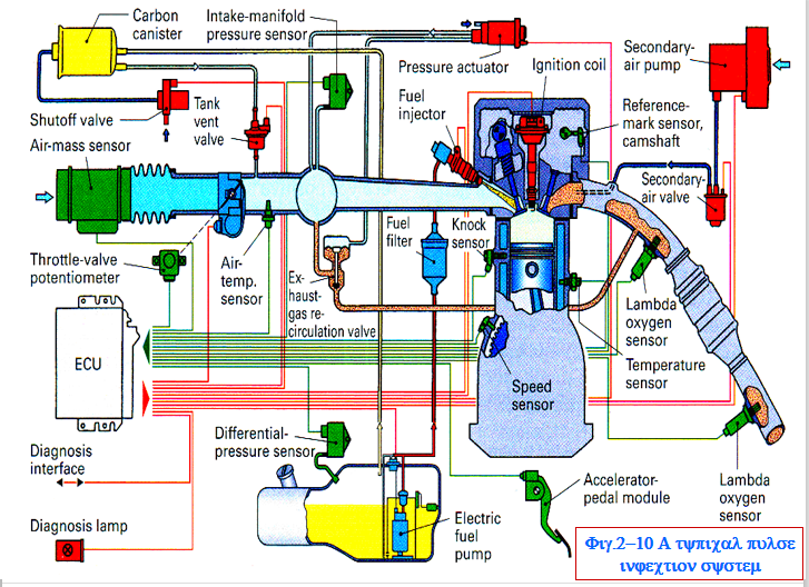
3) Electrical Flow System
At the heart of the electrical system (Fig. 234) is the electronic control unit(ECU) This receives electronic signals from various types of sensor that continually monitor engine operating conditions. These input signals relate to the quantity and temperature of intake air, opening of the throttle valve, engine speed, temperature of coolant and starting operation. Armed with this flow of information, the electronic control unit is then capable not only of computing from information stored in its memory the quantity of fuel that needs to be injected into the engine intake ports, but also of providing the necessary output signals to activate the fuel injectors.
All injectors receive their activating signal from the control unit simultaneously. The required fuel quantity is attained after fuel injection is made twice during one complete four stroke cycle of the engine, which is once for every revolution of the crankshaft.
4 Gasoline Direct Injection
The gasoline direct injcection (GD1) engine operates in two distinct combustion modes, these being designated"Ultra-Lean Combustion Mode” and"Superior Output Mode” (Fig. 2.2-35). This particular strategy aims to reduce overall fuel consumption,as Compared to an equivalent indirect-injection petrol engine, and therefore provides a more environment-friendly engine but without sacri-ficing car performance.
In Superior Output Mode, air is drawn in through the upright straight intake port. Fuel is injected in a wide. conical shower during the piston's intake stroke, when it is descending toward the bottom of the cylinder. The vaporization of the fuel cools the air inside cylinder,causing The cylinder itself to cool and thus increasing the compression ratio. The intake port assists by functioning like a supercharger,smoothly drawing in additional air and improving volumetric efficiency,the rising piston carries the homogenous air/tuel mixture upto the spark plug for igniition. turn the GDI engine into a formidable power plant capable of producing 10% higher torque than a Conventional engine of similar displacement.
In Ultra-Lean Combustion Mode. air is drawn in through the upright straight intalke port. the piston rises during compression,causing the air to break up into small vortices, ensuring efficient combustion Fuel is iniected in a compact, beaded spray of the compression strokeover the piston crown during the latter stages of the compression stroke and evaporates in the piston cavity. The air/fuel mixture is carried up to the spark plug immediaitely, and ignited in an optimally stratified form. Because the petrol is burned cleanly and completely,stable combustion is possible even at an Ultra-Lean air/fuel ratio.
5 Electronic throttle control
Another innovation is a'drive-by-wire' contol for fuel ijection systems ,generally termed electronic throttle control.Its main purpose is to eliminate the need for a cable control to connect the accelerator pedal with the system throttle valve. Otherwise this involves routing the cable through the bulkhead to the body interior, making it a potential source of noise transmission.A further benefit of using an electronic throttle control is enable the driver's commands to be moderated, via an electroniccontrol module.This receives inputs from the engine management and other systems, such as traction and stability controls, and can therefore contibute to improved driveability stability and also emissions reduction.
In practice. the eletronice thorle control system comprises three modules: accelerator pedal,throttle servo motor and electronic controls ( Fig 2-36). Accelerator pedal movements are monitored by position sensors and the information communicated to the electronic control module. The throttle valve plate receives its turning movements from a DC electric motor, via a double-reduction gearset that engages with a quadrant gear on the throttle plate spindle. This combination of electric servo motor and reduction gearing provides responsive and precise angular positioning of the throttle plate to regulate air flow, together with sufficient torque capacity to overcome any sticking tendency. The throtle valve positioning is also monitored by sensors, which likewise communicate the information to the electronic control module.

