valve system
1 valve Train
To coordinate the four-stroke cycle, a group of parts called the valve train opens and closes the valves(moves them down and up,respectively).these valve movements must take place at exactly the right moments.the opening of each valve is controlled by a camshaft.there are different types of valve trains depending on how many camshafts are and where they are lacated.
1) Overhead camshaft (OHC)valve train
The cam is an egg-shaped piece of metal on a shaft that rotates in coordination with the crankshaft. The metal shaft, called the camshaft, typically has individual cams for each valve in the engine. As the camshaft rotates, the lobe, or high spot of the cam, pushes against parts connected to the stem of the valve. This action forces the valve to move downward. This action could open an inlet valve for an intake stroke, or open an exhaust valve for an exhaust stroke.
Valve in modern car engines are located in the cylinder head at top of the engine.this is know as an overhead valve(OHV) configuration.in addition,when the camshaft is located over the cylinder head,the arrangement is known as an overhead camshaft(OHC)design.some high-performance engines have two separate camshaft,one foreach set of inlet and exhaust valves.These engine are known as dual overhead-canshaft (DHOC)engine.
2) push-rod valve train
The camshaft also can located in the lower part of the engine,within the engine block to transfer the motion of the cam upward to valve,additional parts are needed.
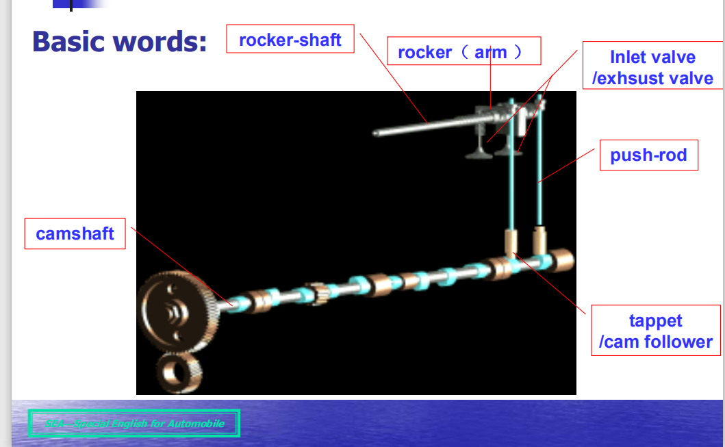
In this arrangement, the cam lobes push against round metal cylinders called cam follower. As the lobe of the cam comes up under the cam follower, it pushes the cam follower upward (away from the camshaft). The cam follower rides against a push rod, which pushes against a rocker arm. The rocker arm pivots on a shaft through its center. As one side of the rocker arm moves up, the other side moves down, just like a seesaw. The downward-moving side of the rocker arm pushes on the valve stem to open the valve.
Because a push-rod valve train has additional parts,it is more difficult to run at high speeds.push-rod engine typically run at slower speeds and,consequently,produce less horse-power than overhead-camshaft designs of equal size.(remember,power is the rate at which work is done.)
2 Valve clearance
When the engine runs in compression stroke and power stroke, the valves must close tightly on their seats to produce a gas-tight seal and thus prevent the gases escaping from the combustion chamber. If the valves do not close fully the engine will not develop full power.Also the valve heads will be liable to be burnt by the passing hot gases, and there is the likelihood of the piston crown touching an open valve, which can seriously damage the engine.
So that the valves can close fully some clearance is needed in the operating mechanism.this means that the operating mechanism must be able to move sufficiently far enough away from the valve to allow the valves to be fully closed against its seat by the valve spring.however,if the clearance is set too great this will cause a light metallic tapping noise.
3 valve timing
The time at which valves open and close ( valve timing ) and the duration of the valve opening is stated in degrees of crankshaft rotation . For example , the intake valve normally begins to open just before the piston has reached the top dead center . The valve remains open as the piston trave ls down to BDC and even past BDC . This is intake valve duration .An example of this could be stated as follows : IO at 17°BTDC , IC at 51°ABDC ( or , intake opens 17°before top dead center , intake closes 51°after bottom dead center ) . Intake valve duration in this case is 248° of crankshaft rotation .
This leaves 129° duration for the compression stroke since compression ends when the piston reaches TDC . At this point the power stroke begins . The power stroke ends when the exhaust valve begins to open approximately at 51° before bottom dead center . The duration of the power strokein this case is also 129°.
Since the exhaust valve is opening at 51°BBDC , this begins the exhaust stroke . The exhaust stroke continues as the piston passes BDC and moves upward to past TDC . With the exhaust valve closing at 17°TTDC , the duration of the exhaust stroke is 248°.
It is apparent from this description that the exhaust valve stays open for a short period of time during which the intake valve is also open . In other words , the end of the exhaust stroke and the beginning of the intake stroke overlap for a short period of time . This is called valve overlap . Valve timing and valve overlap vary on different engines.
Opening the intake valve before TDC and closing it after BDC increase the fill of air-fuel mixture in the cylinder . Opening the intake valve early helps overcome the static inertia of the air-fuel mixture at the beginning of the intake stroke , while leaving the intake valve open after BDC takes advantage of the kinetic of the moving air-fuel mixture . This increase volumetric efficiency.
As the piston moves down on the power stroke past the 90°ATDC position , pressure in the cylinder has dropped , and the leverage to the crankshaft has decreased due to connecting rod angle and crankshaft position . This ends the effective length of the power stroke , and the exhaust valve can now be opened to begin expelling the burned gases . The exhaust valve remains open until the piston has moved up past the TDC position . This helps to remove as much of the burned gases as is possible and increase volumetric efficiency .
4 Cam design and control dynamic
The function of the cam is to open and close the valves as far as possible,as fast as possible and as smoothly as possible.The closing force for the valves is applied by the valve springs which also maintain contact between the cam and the valves.Dynamic force impose limits on cam and valve lift.
The entire valve-train assembly can be viewed as a spring/mass system in which the conversion from stored to free energy causes force vibration.Valve-train assemblies with overhead camshafts can be represented with sufficient accuracy by a 1-mass system(consisting of the moving mass,the valve-train assembly stiffness and corresponding damping).For system with valve bottom-mounted camshafts and push rods,a 2-mass system is being increasingly used.
The maximum permissible contact stress,usually regarded as the parameter which limits cam-lobe radius and the rate of opening on the flank,currently lies between 600-750Mpa depending upon the material parings used.
5 Camshaft Drive Mechanism
Each cam must revolve once during the four-stroke cycle to open a valve.A cycle,remember,corresponds with two revolutions of the crankshaft.Therefore,the camshaft must revolve at exactly half the speed of the crankshaft.This is accomplished with a 2:1 gear ratio.A gear connected to the camshaft has twice the number of teeth as a gear connected to the crankshaft.The gears are linked in one of three ways:

1) Belt Drive
A cog-type belt can be used.Such belts are made of synthetic rubber and reinforced with internal steel or fiberglass strands.The belts have teeth,or slotted spaces to engage and drive teeth on gear wheels.A belt typically is used on engines with overhead-cam valve trains.
2) Chain Drive
On some engines,a metal chain is used to connect the crankshaft and camshaft gears. Most push-rod engines and some OHC engines have chains.
3) Gear Drive
The camshaft and crankshaft gears can be connected directly,or meshed.This type of operating linkage commonly is used on older six-cylinder,inline engines.
A camshaft driven by a chain or belt turns in the same direction as the crankshaft.But a Camshaft driven directly by the crankshaft gear turns in the opposite direction.Timing belts are used because they cost less than chains and operate more quietly.A typical timing belt is made of neoprene(synthetic rubber)reinforced with fiberglass.
6 Electronic valve control system
An electronic value control (EVC) system replaces the mechanical camshaft,controlling each value with actuators for independent value timing.The EVC system controls the opening and closing time and lift amount of each intake and exhaust valve with independent actuators on each value.Changing from a mechanical camshaft driven value into independently controlled actuator valves provides a huge amount of flexibility in engine control strategy. Vehicles utilizing EVC can realize several benefits including:
1) increases engine power and fuel economy; 2) allows centralized and distributed EVC systems to perform at their full potential; 3) adapts to engines of varied cylinder counts.
With all of the improved efficiencies and consumer benefits,auto manufacturers are eager to get their first EVC systems on the road. The EVC system is targeted to operate in temperatures up to 125℃,while the actuator is targeted to run up to 6000r/min.The actuator can be controlled in a centralized system with a high-speed multiplex bus (up to 10Mbps) or in a distributed system with a nominal speed bus.
EVC systems must be compact in size,specifically the actuators that must be small enough to fit in the engine space.A vehicle that uses a 42V system is ideal for EVC because it requires high voltage to control the value actuators, and EVC is targeted for V8 and V12 engines.The EVC system is also highly flexible,allowing adaptability for a number of cylinder engines.