piston, connecting rod and crankshaft

1 Piston assembly
The piston is an important part of a four-stroke cycle engine. Most pistons are made from cast aluminum. The piston , through the connecting rod, transfers to the crankshaft the force created by the burning fuel mixture. This force turns the crankshaft .Thin, circular , steel bands fit into grooves around the piston to seal the bottom of the combustion chamber. These bands are called piston rings. The grooves into which they fit are called ring grooves. A piston pin fits into a round hole in the piston . The piston pin joins the piston to the connecting rod . The thick part of the piston that holds the piston is the pin boss.
1) Piston
To withstand the heat of the combustion chamber,the piston must be strong. It also must be light, since it travels at high speeds as it moves up and down inside the cylinder. The piston is hollow. It is thick at the top where it take the brunt of the heat and the expansion force. It is thin at the bottom, where there is less heat. The top part of the piston is the head , or crown . The thin part is the skirt The sections between the ring grooves are called ring lands.
In disel engines, the combustion chamber may be formed totally or in part in the piston crown, depending on method of injection.
2) Piston rings
As Fig.2-9 shows , piston rings fit into ring grooves near the of the piston. In simplest terms, piston rings are thin, circular pieces of metal that fit into grooves in the tops of the pistons.
In modern engines, each piston has three rings. (Piston in older engines sometimes had four rings, or even five.) The inside surface of the ring fits in the groove on the piston. The ring's outside surface presses against the cylinder walls.That is, only the rings contact the cylinder walls.The top two rings are to keep the gases in the cylinder and are called compression rings. it twists slightly upwards. During intake the ring scrapes surface oil off the walls, during compression,it tends to slide over the oil and not carry it into the combustion chamber. In the power stroke, combustion pressure forces down on the top of the ring and also against its back,so that it has full-face contact with the cylinder walls for effective sealing.
The lower ring prevents the oil splashed onto the cylinder bore from entering the combustion chamber , and is called an oil ring.Chrome-face cast-iron compression rings are commonly used in automobile engines. The chrome face provide a very smooth , wear-resistant surface.
During the power stoke , combustion pressure on the combustion rings is very high. It causes them to untwist . Some of the high-pressure gas gets in back of the rings. This force the ring face into full contact with the cylinder wall. The combustion pressure also holds the bottom of the ring tightly against the bottom of the ring groove. Therefore , high combustion pressure causes a tighter seal between the ring face and the cylinder wall.
3) Piston Pin
The piston pin holds together the piston and the connecting rod . This pin fits into the piston pin holes and into a hole in the top end of the connecting rod. The top end of is much smaller than the end that fits on the crankshaft . This small end fits inside the bottom of the piston . The piston pin fits through one side of the piston , through the small end of the rod , and then through the other side of the piston . It holds the rod firmly in place in the center of the piston. Pins are made of high-strength steel and have a hollow center . Many pins are chrome-plated to help them wear better.
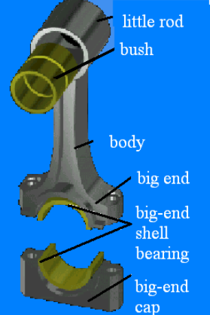
4) Connecting rod
The connecting rod is made of forged high-strength steel . It transmits and motion from the piston to the crankpin on the crankshaft . The connecting rod little end is connected to the piston pin . A bush made from a soft metal , such as bronze , is used for this joint . The lower end of the connecting rod fits the crankshaft journal . This is called the big end . For this big-end bearing , steel-backed lead or tin shell bearings are used . These are the same as those used for the main bearings . The split of the big end is sometimes at an angle , so that it is small enough to be withdrawn through the cylinderbore . The connecting rod is made from forged alloy steel .
5) Crankshaft
The crankshaft , in conjunction with the connecting rod , coverts the reciprocating motion of the piston to the rotary motion needed to drive the vehicle . It is usually made from carbon steel which is alloyed with a small proportion of nickel .The main bearing journals fit into the cylinder block and the big end journals align with the connecting rods .At the rear end of the crankshaft is attached the flywheel , and at the front end are the driving whells for the timing gears , fan , cooling water and alternator .
The throw of the crankshaft , i.e. the distance between the main journal and the big end centers ,controls the length of the stroke . The stroke is double the throw , and the stroke-length is the distance that the piston travels from TDC to BDC and vice versa .
5) Cylinder numbering and firing order
A single-cylinder engine provide only one power impulse for every two-crankshaft revolution.the engine is delivering power only one-fourth of the time.a smoother flow power from the crank-shaft is obtained when more than one cylinder is used.
The arrangement of the crankthrows is also determined by the requirements for even firing intervals of the cylinders and for spacing the sucessive power impulses as far apart as possible along the crankshaft, so as to reduce torsional deflections or twisting effects. For any four-stroke engine the firing intervals must,if they are to be even,be equal to 720°divided by the number of cylinders。
For in-line four-cylinder engines the first and fourth crankthrows are therefore indexed on oneside of the crankshaft and the second and third throws on the other side.The firing order of these engines,numbering from the front,may then either 1-3-4-2 or 1-2-4-3 at 180° intervals
Similarly,in the case of in-line six-cylinder engines, the crankthrows are spaced in pairs with an angle of 120° between them.Hence, the first and sixth are paired, as are the second and fifth, and like-wise the third and fourth. The firing order may then be such that no two adjacent cylinders fire in succession; that is,either 1-5-3-6-2-4 or 1-4-2-6-3-5 at, of course, 120° intervals.
6) Flywheel
The flywheel is the made from carbon steel . It fits onto the rear of the crankshaft . As well as keeping the engine rotating between power strokes it also carries the clutch , which transmits the drive to the transmission , and has the starter ring gear around its circumference . There is only one working stroke in four so a flywheel is needed to drive the crankshaft during the time that the engine is performing the non-power strokes.
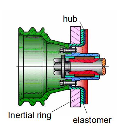
7) Torsional vibration balancer
The inertia ring is bonded to the hubthrough a flexible elastomer (rubber compound) insert. The inertial ring moves slightly in relation tocrankshaft rotation as each cylinder fires, thereby dampening the torsionalvibration of the crankshaft over a wide range of engine speed.