目录

  • 1 Basic Concepts of Electric Circuits
    • 1.1 Introduction
    • 1.2 Voltage and Current
    • 1.3 Power and Energy
  • 2 Basic Laws of Electric Circuit
    • 2.1 Ohm's Law
    • 2.2 Kirchhoff's Laws
    • 2.3 Series Resistors and Voltage Division
    • 2.4 Parallel Resistors and Current Division
    • 2.5 Summary
  • 3 Capacitors and Inductors
    • 3.1 Capacitors
    • 3.2 Inductors
    • 3.3 Summary
  • 4 Electronic System
    • 4.1 Introduction
    • 4.2 Electronic System Block Diagrams
    • 4.3 Information Processing Versus Power Electronics
    • 4.4 Analog Versus Digital Systems
    • 4.5 Conversion of Signals from Analog to Digital Form
    • 4.6 Relative Advantages of Analog and Digital Systems
  • 5 Operational Amplifiers
    • 5.1 Introduction
    • 5.2 Operational Amplifiers
    • 5.3 Ideal op-amp
    • 5.4 Inverting Amplifier
    • 5.5 Noninverting Amplifier
  • 6 Digital Logic Circuits
    • 6.1 Basic Concepts and Introduction
    • 6.2 Electrical Specifications for Logic Gates
  • 7 Transformer
    • 7.1 Introduction
    • 7.2 Construction of Transformer
    • 7.3 The Ideal Transformer
  • 8 Electrical Machines
    • 8.1 A Brief Overview
    • 8.2 Induction Machines
    • 8.3 Synchronous Machines
    • 8.4 Direct-Current Machines
  • 9 Automatic Control Systems
    • 9.1 Introduction
    • 9.2 Block Diagrams and Transfer Functions
    • 9.3 Open-Loop Control
    • 9.4 Closed-Loop Control: Feedback
    • 9.5 Objectives of a Control System
    • 9.6 Assignment
  • 10 Measurement
    • 10.1 Introduction
    • 10.2 Statistics
    • 10.3 Operating Characteristics
    • 10.4 Measurement Instruments
    • 10.5 Velocity Measurement
  • 11 Power Semiconductor Switches
    • 11.1 Introduction
    • 11.2 Thyristors
    • 11.3 Metal-Oxide-Semiconductor Field Effect Transistors
    • 11.4 Gate Turn-Off Thyristors
    • 11.5 Insulated Gate Bipolar Transistors
    • 11.6 Desired Characteristics in Controllable Switches
  • 12 Rectifiers and Inverters
    • 12.1 Introduction
    • 12.2 Basic Rectifier Concepts
    • 12.3 Practical Thyristor Converters
  • 13 Academic English
    • 13.1 Vocabulary
    • 13.2 Structure
    • 13.3 Common errors
Electronic System Block Diagrams

Block diagram of system

The block diagram for the simple system is shown below, with individual inputs and outputs

Block Diagram Representation

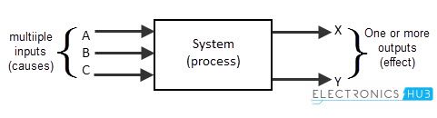
The electronic system may have multiple inputs and multiple outputs. The system accepts the inputs and it processes the required task to produce the outputs. The state of the system can be changed by processing the inputs. So the inputs are the “cause” of change in system’s equilibrium state.

This means the inputs and outputs of a system are in an direct relationship that inputs will show effect on outputs. This analysis of control system is called as “Cause and Effect analysis”.

An audio system, TV, or any Mp3 player is the example of an electronic system. The sound waves are converted to electrical signals and they are amplified to process the output of high strengthened audio signals, through speakers.