How a Capacitor Is Made
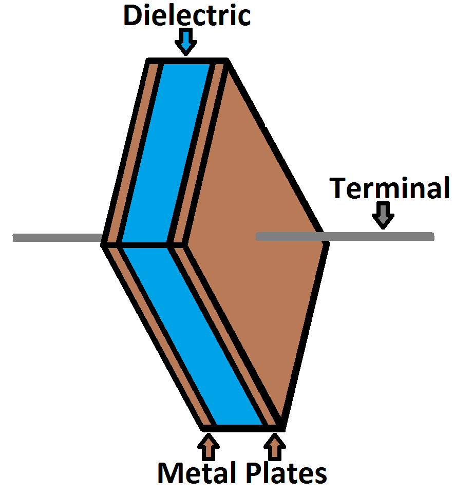
The schematic symbol for a capacitor actually closely resembles how it’s made. A capacitor is created out of two metal plates and an insulating material called a dielectric. The metal plates are placed very close to each other, in parallel, but the dielectric sits between them to make sure they don’t touch.

Your standard capacitor sandwich: two metal plates separated by an insulating dielectric.
The dielectric can be made out of all sorts of insulating materials: paper, glass, rubber, ceramic, plastic, or anything that will impede the flow of current.
The plates are made of a conductive material: aluminum, tantalum, silver, or other metals. They’re each connected to a terminal wire, which is what eventually connects to the rest of the circuit.
The capacitance of a capacitor – how many farads it has – depends on how it’s constructed. More capacitance requires a larger capacitor. Plates with more overlapping surface area provide more capacitance, while more distance between the plates means less capacitance. The material of the dielectric even has an effect on how many farads a cap has. The total capacitance of a capacitor can be calculated with the equation:
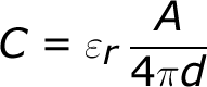
Where εr is the dielectric’s relative permittivity (a constant value determined by the dielectric material), A is the amount of area the plates overlap each other, and d is the distance between the plates.
How a Capacitor Works
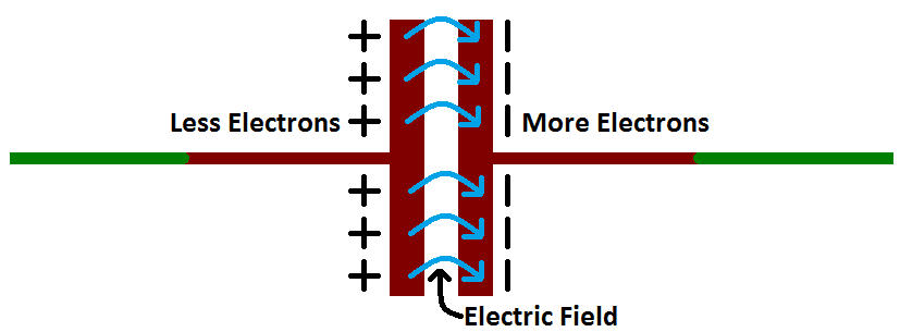
Electric current is the flow of electric charge, which is what electrical components harness to light up, or spin, or do whatever they do. When current flows into a capacitor, the charges get “stuck” on the plates because they can’t get past the insulating dielectric. Electrons – negatively charged particles – are sucked into one of the plates, and it becomes overall negatively charged. The large mass of negative charges on one plate pushes away like charges on the other plate, making it positively charged.

The positive and negative charges on each of these plates attract each other, because that’s what opposite charges do. But, with the dielectric sitting between them, as much as they want to come together, the charges will forever be stuck on the plate (until they have somewhere else to go). The stationary charges on these plates create an electric field, which influence electric potential energy and voltage. When charges group together on a capacitor like this, the cap is storing electric energy just as a battery might store chemical energy.
Charging and Discharging
When positive and negative charges coalesce on the capacitor plates, the capacitor becomes charged. A capacitor can retain its electric field – hold its charge – because the positive and negative charges on each of the plates attract each other but never reach each other.
At some point the capacitor plates will be so full of charges that they just can’t accept any more. There are enough negative charges on one plate that they can repel any others that try to join. This is where the capacitance (farads) of a capacitor comes into play, which tells you the maximum amount of charge the cap can store.
If a path in the circuit is created, which allows the charges to find another path to each other, they’ll leave the capacitor, and it will discharge.
For example, in the circuit below, a battery can be used to induce an electric potential across the capacitor. This will cause equal but opposite charges to build up on each of the plates, until they’re so full they repel any more current from flowing. An LED placed in series with the cap could provide a path for the current, and the energy stored in the capacitor could be used to briefly illuminate the LED.
Calculating Charge, Voltage, and Current
A capacitor’s capacitance – how many farads it has – tells you how much charge it can store. How much charge a capacitor is currently storing depends on the potential difference (voltage) between its plates. This relationship between charge, capacitance, and voltage can be modeled with this equation:

Charge (Q) stored in a capacitor is the product of its capacitance (C) and the voltage (V) applied to it.
The capacitance of a capacitor should always be a constant, known value. So we can adjust voltage to increase or decrease the cap’s charge. More voltage means more charge, less voltage…less charge.
That equation also gives us a good way to define the value of one farad. One farad (F) is the capacity to store one unit of energy (coulombs) per every one volt.
Calculating Current
We can take the charge/voltage/capacitance equation a step further to find out how capacitance and voltage affect current, because current is the rate of flow of charge. The gist of a capacitor’s relationship to voltage and current is this: the amount of current through a capacitor depends on both the capacitance and how quickly the voltage is rising or falling. If the voltage across a capacitor swiftly rises, a large positive current will be induced through the capacitor. A slower rise in voltage across a capacitor equates to a smaller current through it. If the voltage across a capacitor is steady and unchanging, no current will go through it.
(This is ugly, and gets into calculus. It’s not all that necessary until you get into time-domain analysis, filter-design, and other gnarly stuff, so skip ahead to the next page if you’re not comfortable with this equation.) The equation for calculating current through a capacitor is:
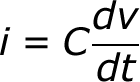
The dV/dt part of that equation is a derivative (a fancy way of saying instantaneous rate) of voltage over time, it’s equivalent to saying “how fast is voltage going up or down at this very moment”. The big takeaway from this equation is that if voltage is steady, the derivative is zero, which means current is also zero. This is why current cannot flow through a capacitor holding a steady, DC voltage.